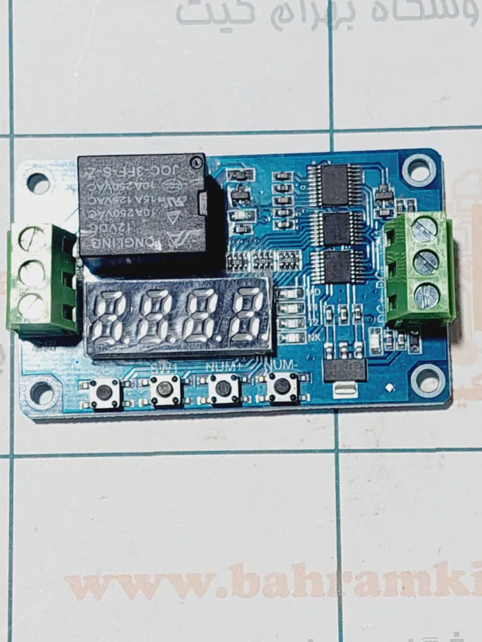
ماژول تایمر drm01 با 15 عملکرد
۲۴۰,۰۰۰ تومان
راهنمای کاربر ماژول تایمر drm01 با 15 عملکرد یا ماژول رله تایمر (FRM01):
ماژول تایمر drm01 با 15 عملکرد یا ماژول کنترل رله چند منظوره (FRM01)، طراحی شده برای مشتریان با نیازهای مختلف، میکروکنترلر به عنوان واحد کنترل اصلی، 18 نوع عملکرد را از پیش تنظیم کرده است و می تواند بر اساس نیازهای کاربر باشد، شخصی سازی کند و سایر عملکردهای خاص را برای کاربر اضافه کند.
ماژول تایمر drm01 با 18 عملکرد با استفاده از ماژول رله توان با کیفیت بالا، ترانزیستور پرتوان و ولتاژ بالا، چراغ های سیگنال قرمز و آبی، برد PCB دو طرفه، عملکرد پایدار، می تواند به طور گسترده در موارد مختلف کنترل توان استفاده شود.
عملکرد ماژول تایمر drm01 با 15 عملکرد
کاربر می تواند یکی از 18 نوع عملکرد زیر را با توجه به کلیدها و صفحه نمایش انتخاب کند، می تواند پارامترهای 18 نوع عملکرد را تنظیم و ذخیره کند، همچنین می تواند پارامترهای عملکرد فعلی ، پارامتر زمان تنظیم حداقل 0.1 ثانیه قابل تنظیم می باشد، و عملکرد تخصصی بیشتر را مشاهده کند.
یادآوری ظریف: عملکرد 1-8 پس از روشن شدن به طور خودکار شروع می شوند. عملکرد 9-18 شروع به یک پالس سیگنال تریگر سطح بالا و دوره سطح بالا ≥20ms نیاز دارد.
عملکرد 9 حالت قفل خودکار است. عملکرد 10 یک حالت کنترل سطح است.
در انبار موجود نمی باشد
ماژول تایمر drm01 با 15 عملکرد
1
راهنمای کاربر ماژول تایمر drm01 با 18 عملکرد یا ماژول رله تایمر (FRM01):
ماژول تایمر drm01 با 15 عملکرد یا ماژول کنترل رله چند منظوره (FRM01)، طراحی شده برای مشتریان با نیازهای مختلف، میکروکنترلر به عنوان واحد کنترل اصلی، 18 نوع عملکرد را از پیش تنظیم کرده است و می تواند بر اساس نیازهای کاربر باشد، شخصی سازی کند و سایر عملکردهای خاص را برای کاربر اضافه کند.
ماژول تایمر drm01 با 15 عملکرد با استفاده از ماژول رله توان با کیفیت بالا، ترانزیستور پرتوان و ولتاژ بالا، چراغ های سیگنال قرمز و آبی، برد PCB دو طرفه، عملکرد پایدار، می تواند به طور گسترده در موارد مختلف کنترل توان استفاده شود.
I.عملکرد ماژول
کاربر می تواند یکی از 18 نوع عملکرد زیر را با توجه به کلیدها و صفحه نمایش انتخاب کند، می تواند پارامترهای 18 نوع عملکرد را تنظیم و ذخیره کند، همچنین می تواند پارامترهای عملکرد فعلی ، پارامتر زمان تنظیم حداقل 0.1 ثانیه قابل تنظیم می باشد، و عملکرد تخصصی بیشتر را مشاهده کند.
یادآوری ظریف: عملکرد 1-8 پس از روشن شدن به طور خودکار شروع می شوند. عملکرد 9-18 شروع به یک پالس سیگنال تریگر سطح بالا و دوره سطح بالا ≥20ms نیاز دارد.
عملکرد 9 حالت قفل خودکار است. عملکرد 10 یک حالت کنترل سطح است.
[عملکرد 1]:
زمان Pull-in: پس از روشن شدن، زمانی که زمان تنظیم T1 رسید، رله Pull-in و T1 می توانند بین 0.1 ثانیه تا 270 ساعت قابل تنظیم باشند، به رابط CH1 یک سیگنال پالس بالا (دوره سطح بالا ≥20 میلی ثانیه) می دهید. عملکرد بالا را تکرار کنید.
[عملکرد 2]:
زمان قطع: پس از روشن شدن رله pull-in، زمانی که زمان تنظیم T1 رسید، رله قطع میشود و T1 میتواند بین 0.1 ثانیه تا 270 ساعت قابل تنظیم باشد، به رابط CH1 یک سیگنال پالس بالا میدهید (مدت زمان سطح بالا ≥20 میلیثانیه) ، عملکرد بالا را تکرار کنید.
[عملکرد 3]:
زمانبندی Pull-in سپس قطع: پس از روشن شدن، رله pull-in کار نمی کند، زمانی که زمان تنظیم T1 رله pull-in رسید. با رسیدن زمان تنظیم، رله T2 قطع می شود، و T1 و T2 می توانند بین 0.1 ثانیه -270 ساعت قابل تنظیم باشند، به رابط CH1 سیگنال پالس بالایی می دهند (مدت زمان سطح بالا ≥20 میلی ثانیه)، عملکرد بالا را تکرار کنید.
2
[عملکرد 4]:
زمان قطع هنگام Pull-in: پس از روشن شدن، رله بلافاصله pull-in می شود، پس از رسیدن زمان تنظیم، رله T1 قطع می شود. هنگامی که زمان تنظیم رله T2 رسید رله pull-in، و T1 و T2 را می توان بین 0.1 ثانیه تا 270 ساعت تنظیم کرد، به رابط CH1 سیگنال پالس بالایی داد (مدت زمان سطح بالا ≥20 میلی ثانیه)، عملکرد بالا را تکرار کنید.
[عملکرد 5]:
تایمینگ چرخه نامحدود حالت A: پس از روشن شدن، رله Pull-in کار نمی کند، زمانی که زمان تنظیم T1 رله Pull-in. هنگامی که زمان تنظیم رله T2 قطع می شود، سپس وضعیت فوق را تکرار کنید، و T1 و T2 را می توان بین 0.1 ثانیه -270 ساعت تنظیم کرد، به رابط CH1 سیگنال پالس بالا بدهید (مدت زمان سطح بالا ≥20 میلی ثانیه)، عملکرد فوق را تکرار کنید.
[عملکرد 6] :
تایمینگ چرخه نامحدود حالت B: پس از روشن شدن، رله بلافاصله pull-in می شود، زمانی که زمان تنظیم رله T1 رسید، رله قطع می شود. هنگامی که زمان تنظیم رله T2 رسید، سپس وضعیت فوق را تکرار کنید، و T1 و T2 را می توان بین 0.1 ثانیه -270 ساعت تنظیم کرد، به رابط CH1 سیگنال پالس بالا (مدت زمان سطح بالا ≥20 میلی ثانیه) بدهید، عملکرد فوق را تکرار کنید.
[عملکرد 7]:
تایمینگ چرخه محدود حالت A: پس از روشن شدن، رله Pull-in کار نمی کند، زمانی که زمان تنظیم T1 رله Pull-in می شود. هنگامی که زمان تنظیم قطع رله T2 رسید، سپس وضعیت فوق را بارها “NX” بار تکرار کنید، T1 و T2 را می توان بین 0.1 ثانیه -9999 ثانیه تنظیم کرد، زمان چرخه “NX” را می توان بین 1-9999 تنظیم کرد، رابط CH1 را ارائه می دهد. یک سیگنال پالس بالا (مدت زمان سطح بالا ≥ 20 میلی ثانیه)بدهید، عملکرد بالا را تکرار کنید.
[عملکرد 8]:
تایمینگ چرخه محدود حالت B: پس از روشن شدن، بلافاصله رله pull-in می شود، پس از رسیدن زمان تنظیم رله T1 قطع می شود. هنگامی که زمان تنظیم رله T2 رسید رله pull-in، سپس وضعیت فوق را بارها “NX” تکرار کنید، T1 و T2 را می توان بین 0.1 ثانیه -9999 ثانیه تنظیم کرد، زمان چرخه “NX” را می توان بین 1-9999 تنظیم کرد. رابط CH1 را ارائه می دهد. یک سیگنال پالس بالا (مدت زمان سطح بالا ≥ 20 میلی ثانیه)بدهید، عملکرد بالا را تکرار کنید.
[عملکرد 9] :
حالت قفل خودکار: به رابط CH1 یک سیگنال پالس بالا بدهید، رله Pull-in ، دوباره یک سیگنال پالس بالا بدهید، رله قطع شود.
[عملکرد 10]:
حالت تریگر: دارای عملکرد خاموش تاخیری است، رله پس از روشن شدن کار نمی کند، به رابط CH1 یک سیگنال پالس بالا می دهید، رله فوراً pull-in می شود، زمانی که سیگنال پالس بالا ناپدید شد، رله همچنان pull-in, به هنگام رسیدن زمان تنظیم T1 رله قطع می شود. زمان قطع رله T1، T1 را می توان بین 0 ثانیه تا 270 ساعت تنظیم کرد.
نکته: در این عملکرد، اگر T1 صفر ثانیه است، به کانکتور CH1 یک سیگنال پالس بالا بدهید. رله pull-in، هنگامی که سیگنال پالس بالا ناپدید شد، رله بلافاصله قطع می شود.
3
[عملکرد 11]:
حالت تایمینگ تریگر A: رله پس از روشن شدن کار نمی کند، به کانکتور CH1 یک سیگنال پالس بالا می دهد، زمانی که زمان تایم T1 رسید، رله Pull-in , زمان T1 می تواند بین 0.1 ثانیه تا 270 ساعت قابل تنظیم باشد، یک سیگنال پالس بالا بدهید، عملکرد بالا را تکرار کنید.
[عملکرد 12]:
حالت زمانبندی تریگر B: رله پس از روشن شدن کار نمیکند، به رابط CH1 سیگنال پالس بالا میدهد، رله Pull-in ، زمانی که زمان T1 رسید، رله قطع، T1 را میتوان بین 0.1 ثانیه تا 270 ساعت تنظیم کرد. دوباره به رابط CH1 یک سیگنال پالس بالا بدهید، عملکرد بالا را یک بار تکرار کنید.
[عملکرد 13]:
حالت تایمینگ تریگر C: رله پس از روشن شدن کار نمی کند، به رابط CH1 یک سیگنال پالس بالا می دهد، زمانی که زمان تایمینگ T1 رسید، رله Pull-in، زمانی که زمان تایمینگ T2 رسید، رله قطع می شود، زمان تایمینگ T1 و T2 می تواند بین 0.1 ثانیه تا 270 ساعت قابل تنظیم باشد، دوباره سیگنال پالس بالا را به رابط CH1 بدهید، عملکرد بالا را یک بار تکرار کنید.
[عملکرد 14]:
حالت تایمینگ تریگر D: رله پس از روشن شدن کار نمی کند، به رابط CH1 سیگنال پالس بالا می دهد، فوراً رله Pull-in می شود ، هنگامی که زمان تایمینگ T1 رسید، رله قطع می شود، هنگامی که زمان تایمینگ T2 رسید، رله pull-in، زمان T1 و T2 را می توان بین 0.1 ثانیه تا 270 ساعت تنظیم کرد، دوباره سیگنال پالس بالا را به رابط CH1 بدهید، عملکرد بالا را یک بار تکرار کنید.
[عملکرد 15]:
حالت زمانبندی چرخه نامحدود A: رله پس از روشن شدن کار نمیکند، به کانکتور CH1 یک سیگنال پالس بالا بدهید، زمانی که زمان تایمینگ T1 رسید، رله pull-in، زمانی که زمان تایمینگ T2 رسید، رله قطع شود، سپس وضعیت فوق را تکرار کنید، زمان T1 و T2 را می توان بین 0.1 ثانیه تا 270 ساعت تنظیم کرد، دوباره سیگنال پالس بالا را به رابط CH1 بدهید، عملکرد بالا را یک بار تکرار کنید.
[عملکرد 16]:
حالت تایمینگ چرخه نامحدود B: رله پس از روشن شدن کار نمی کند، به رابط CH1 سیگنال پالس بالا می دهد، رله بلافاصله پس از رسیدن به زمان تایمینگ T1، رله قطع می شود، زمانی که زمان تایمینگ T2 رسید، رله Pull-in ، سپس وضعیت فوق را تکرار کنید، زمان T1 و T2 را می توان بین 0.1 ثانیه تا 270 ساعت تنظیم کرد، دوباره سیگنال پالس بالا را به رابط CH1 بدهید، عملکرد بالا را یک بار تکرار کنید.
[عملکرد 17]:
حالت تایمینگ سیکل محدود A: رله پس از روشن شدن کار نمی کند، به رابط CH1 سیگنال پالس بالا بدهید، زمانی که زمان تایمینگ رسید، رله Pull-in، زمانی که زمان تایمینگ T2 رسید، رله قطع می شود، سپس وضعیت فوق “NX” را بارها تکرار کنید، T1 و T2 را می توان بین 0.1 ثانیه تا 9999 ثانیه تنظیم کرد. زمان چرخه “NX” را می توان بین 1 تا 9999 تنظیم کرد، دوباره به رابط CH1 یک سیگنال پالس بالا بدهید، عملکرد بالا را تکرار کنید.
4
[عملکرد 18]:
حالت تایمینگ سیکل محدود B: رله پس از روشن شدن کار نمی کند، به رابط CH1 سیگنال پالس بالا بدهید، رله فوراً pull-in می شود، زمانی که زمان تایمینگ T1 رسید، رله قطع می شود، زمانی که زمان تایمینگ T2 رسید، رله pull-in، سپس وضعیت فوق “NX” را بارها تکرار کنید، T1 و T2 را می توان بین 0.1 ثانیه تا 9999 ثانیه تنظیم کرد. زمان چرخه “NX” را می توان بین 1 تا 9999 تنظیم کرد، دوباره به رابط CH1 یک سیگنال پالس بالا بدهید، عملکرد بالا را تکرار کنید.
II. دستورالعمل های اجرایی
کاربر می تواند حالت عملکرد را با توجه به کلیدها و صفحه نمایش انتخاب کند، همچنین می تواند پارامترهای تایمینگ را تنظیم کند، تمام پارامترها می توانند به طور خودکار پس از تنظیم ذخیره شوند.
در زیر برخی از توضیحات اسم در مورد تنظیم پارامتر آورده شده است:
[کلیدها]: 4 کلید وجود دارد، یعنی: [SET] [SWI]، [NUM +] و [NUM-]، کلیدها دارای فشار کوتاه و طولانی هستند، فشار کوتاه به معنای فشار دادن دکمه کمتر از 1 ثانیه است، فشار طولانی به معنی فشار دادن طولانی است. دکمه را بیش از 1 ثانیه فشار دهید.
[حالت عملیاتی]: 3 نوع وجود دارد، یعنی: [حالت عملیاتی]، [حالت مشاهده پارامتر] و [حالت تنظیم پارامتر].
[tube دیجیتال]: 4 صفحه نمایش دیجیتال وجود دارد، برای تنظیم یا مشاهده پارامترهای تایمینگ کاربر استفاده می شود.
[LED]: 4 نشانگر پارامتر آبی، 1 نشانگر پاور قرمز.
[پارامتر کاربر]: 4 نوع پارامتر را می توان تنظیم کرد (4 نور LED آبی برای نشان دادن پارامترهای زیر).
[MD]: نور MD، حالت tube دیجیتال عملکرد برنامه فعلی را نمایش می دهد، در مجموع 18 نوع حالت نمایش برای انتخاب (01-18).
[T1]: نور T1، حالت tube دیجیتال تایمینگ T1 را نشان می دهد، می تواند 0-9999 ثانیه باشد.
[T2]: نور T2، حالت tube دیجیتال تایمینگ T2 را نمایش می دهد، می تواند 0-9999 ثانیه باشد.
[NX]: نور NX، حالت tube دیجیتال معانی مختلف را در عملکردهای مختلف نشان می دهد.
1. در عملکرد 1-6 و 11-16، نور [NX]، tube دیجیتال پایه زمانی T1 و T2 را نشان می دهد، دو tube دیجیتال اول تایمینگ T1 را نشان می دهند و در پشت دو tube دیجیتال تایمینگ T2 را نشان می دهد.
برای مثال:[NX]«01 01» را نشان میدهد به این معنی که واحد زمان 1 ثانیه است.
مثال دیگر: [NX] نشاندهنده “02 01” است یعنی واحد تایمینگ T1 10 ثانیه است، T2 دو ثانیه است، بنابراین حداکثر تایمینگ 9999*99 ثانیه است که حدود 270 ساعت است.
2. در عملکرد 7، 8، 17، 18، نور [NX]، چهار tube دیجیتال تعداد چرخه ها را نشان می دهد، در این لحظه، واحد تایمینگ T1 و T2 یک ثانیه است، بنابراین حداکثر زمان تایمینگ 9999 ثانیه در حالت تایمینگ چرخه محدود است.
5
کلیدها شامل فشار طولانی و فشار کوتاه هستند و در حالتهای مختلف با عملکردهای مختلف، در زیر به معرفی عملکردهای مختلف کلید در سه حالت میپردازیم.
[حالت عملیاتی]:
1. هنگامی که روشن است، شمارش معکوس زمانبندی فعلی نمایشگر دیجیتال، زمانی که زمان صفر است، عدد عملکرد فعلی را نشان میدهد، مانند:“ – – 0 1” به معنای عملکرد 1 است.
2. کوتاه [SET] را فشار دهید , وارد ذخیره سازی پاور کنید، صفحه نمایشگر خاموش میشود، اما برنامه به طور معمول کار میکند، دوباره فشار دهید تا نمایشگر به حالت اول برگردد.
3.طولانی [SET] را فشار دهید و وارد [Parameter setting mode] شوید.
4.طولانی [SWI] را فشار دهید تا وارد [Parameter view mode] شوید.
5. طولانی[NUM+] را به مدت 10 ثانیه فشار دهید در حالت ذخیره پاور خودکار، tube دیجیتال دو بار چشمک می زند، به این معنی که تنظیمات با موفقیت انجام شده است. پس از وارد شدن به حالت صرفه جویی در مصرف انرژی، اگر هیچ دکمه ای در مدت 10 ثانیه عمل نکند، نمایشگر دیجیتال خاموش می شود، اما برنامه در حال اجرا است، می توانید برای بازیابی موقت نمایشگر، شما می تونید کوتاه [SET] را فشار دهید، همچنین می توانید طولانی [NUM+]را دوباره فشار دهید تا از حالت صرفهجویی خودکار برق خارج شوید، tube دیجیتال سه بار چشمک می زند تا نشان دهد که تنظیم با موفقیت انجام شده است.
6. طولانی[NUM-] تایمینگ reset و توقف را فشار دهید، دوباره کوتاه[NUM-] را برای بازیابی زمان فشار دهید، پس از حالت reset، چراغ های LED دیگر چشمک نمی زنند.
[حالت مشاهده پارامتر]:
هنگامی که روشن است، فشار طولانی [SWI] وارد حالت نمایش پارامتر شوید، تحت حالت نمایش پارامتر، می توانید پارامتر عملکرد فعلی را مشاهده کنید، نشانگر LED پارامتر آبی برای نمایش چشمک می زند.
1. کوتاه کلید [SET] را فشار دهید، پارامترها را قطع کنید، می توانید یکی از [MOD]، [T1]، [T2] یا [NX] را انتخاب کنید، نشانگر LED پارامتر انتخاب شده چشمک می زند، tube دیجیتال پارامترها را نمایش می دهد که تنظیم شده اند. مانند: هنگامی که [T1] روشن می شود، tube دیجیتال محتوای [T1] را نمایش می دهد.
2. کلید [SWI] را به مدت طولانی فشار دهید، وارد [حالت عملیاتی] شوید.
[حالت تنظیم پارامتر]:
هنگامی که روشن است، با فشار طولانی [SET] وارد حالت تنظیم پارامتر شوید، در این حالت، می توانید پارامترهای مختلفی را تنظیم کنید، به عنوان مثال، می توانید حالت کار را انتخاب کنید، همچنین می توانید زمان تاخیر و غیره را تنظیم کنید.
1. کوتاه کلید [SET] را فشار دهید، پارامترها را برش دهید، می توانید یکی از [MOD] [T1]، [T2] یا [NX] را انتخاب کنید, نشانگر LED پارامتر انتخاب شده به مدت طولانی روشن می شودخواهد شد،
tube دیجیتال پارامترهای تنظیم شده را نمایش می دهد. همچنین: اگر کاربران نیاز به تنظیم حالت کار دارند، باید [SET] را فشار دهند تا نشانگرهای LED به [MOD] اشاره کنند.
2. کوتاه کلید [SWI] را فشار دهید، tube دیجیتال انتخاب شده، دیجیتال مربوطه را برش دهید tube دیجیتال مربوطه نمایشگر فلش خواهد شد.
3. کوتاه کلید [NUM+] را فشار دهید، tube دیجیتال انتخاب شده عددی +1 است، 9 را برای Stop اضافه کنید.
4. کوتاه کلید [NUM-] را فشار دهید، tube دیجیتال انتخاب شده عددی -1، به 0 کاهش یافته برای Stop می باشد.
5. کلید [SET] را به مدت طولانی فشار دهید، پارامترها را ذخیره کنید و وارد [حالت عملیاتی] شوید.
6
به عنوان مثال:
مثال 1. یک لامپ را به طور خودکار کنترل کنید تا یک ساعت کار کند، سپس خاموش شود. این برنامه می تواند عملکرد 2 یا عملکرد 12 را انتخاب کند، پارامترها را تنظیم کند:
MOD=”- – 12″,T1=”3 6 0 0″,T1=”xxxx”,NX=”0 1 x x ” (x می تواند هر مقداری باشد، نیازی نیست)، در همان زمان، رابط ورودی CH1 به عنوان سوئیچ کاربر، در زیر set-up است.
روند:
1> فشار طولانی [SET] وارد [حالت تنظیم پارامتر] شوید.
2> [SET] را کوتاه فشار دهید، سپس چراغ نشانگر [MOD]، [NUM+] یا [NUM-] را فشار دهید، نمایشگر tube دیجیتال “- – 12″ را تنظیم کنید.
3> فشار کوتاه[SET]، نور T1، تنظیم T1=”3 6 0 0″, T2 نیازی نیست، X10=”0 1 0 1″;
4> [SET] را به مدت طولانی فشار دهید، تنظیمات را ذخیره کنید و از [حالت تنظیم پارامتر] خارج شوید، عملکرد بلافاصله شروع به اجرا می کند.
مثال 2. هنگام روشن شدن، دستگاه 1 ساعت کار می کند، 10 دقیقه توقف می کند، 5 سیکل، دستگاه خاموش می شود.
این برنامه می تواند عملکرد 8 را انتخاب کند، پارامترها را تنظیم کند:MOD=”- – 0 8″, T1=”3 6 0 0″,T2=”0 6 0 0″,NX=”0 0 0 5″.
7
III. مرجع سیم کشی
یادآوری ظریف: اگر کاربر بار و ماژول FRM01 از منبع تغذیه DC شکاف دار استفاده کند، این امکان وجود دارد که ظرفیت منبع تغذیه کافی نباشد یا اتصالات سیم کشی مناسب نباشد، ماژول گاهی اوقات پدیده ناپایدار به نظر می رسد، لطفاً از موارد زیر استفاده کنید (حتی اگر مشکلی پیدا نشد ، باید از توصیه ها پیروی کند):
1. سیم کشی جدا: منبع تغذیه DC مثبت باید دو خط بکشد، یک پیوند FRM01 رابط DC + برای ماژول ها، یک رابط NO برای استفاده در بار، بنابراین منبع تغذیه منفی نیز باید به این صورت برخورد شود.
2. جایگزینی توان جریان خروجی: اگر موتورها و سایر بارهای القایی یا خازنی هستند، ظرفیت برق DC باید بزرگتر را انتخاب کنید، مانند استفاده از موتور 1A، توان 3-5 آمپر برای انتخاب منطقی تر، زیرا شروع موتور جریان 3-7 برابر جریان نامی است، اگر ظرفیت منبع تغذیه خیلی کم باشد، باعث افت فوری ولتاژ می شود و باعث reset ماژول FRM01 می شود.
3. خازن شنت: اگر دو اقدام فوق به اثر مطلوب نرسید، لطفاً شنت خازن های الکترولیتی 470uf/35V یا خازن بالاتر را بین DC-/DC + بگذارید.
IIII. پارامترهای الکتریکی
1. ولتاژ عملیاتی: 5V/12V/24V (+/-10٪)
2. جریان کاری:
5 ولت / کمتر از 90 میلی آمپر (زمانی که رله کمتر از 15 میلی آمپر کار نمی کند، صفحه نمایشگر کمتر از 3 میلی آمپر را خاموش کنید).
12 ولت / کمتر از 50 میلی آمپر (زمانی که رله کمتر از 15 میلی آمپر کار نمی کند، صفحه نمایشگر کمتر از 3 میلی آمپر را خاموش کنید).
24 ولت / کمتر از 35 میلی آمپر (زمانی که رله کمتر از 15 میلی آمپر کار نمی کند، صفحه نمایشگر کمتر از 3 میلی آمپر را خاموش کنید).
3. دمای کاری: -20℃ — 60℃ درجه
4. ظرفیت بار:
ماژول normally open رابط ماکزیمم ظرفیت بار : DC 0 -30V/10A، AC 0-250V/10A.
ماژول normally closed رابط ماکزیمم ظرفیت بار: DC 0-28V/10A، AC 0-125V/10A.
محدودیت ها:
1. عمر رله با عمل 100،000 بار بارگذاری می شود،و بنابراین برای استفاده در کنترل کشش با فرکانس پایین و جریان بالا مناسب تر است. برای استفاده مکرر در موقعیت های اقدام سریع مناسب نیست.
2. توجه داشته باشید حاشیه بار پورت رله را در نظر بگیرید، بار صرفاً مقاومتی بیش از دو برابر به حاشیه چپ، بارهای القایی یا خازنی معمولی باید حداقل سه برابر حاشیه بیشتر باشد.
IV. رابط ماژول
ولتاژ/ورودی سیگنال ماژول: سه رابط وجود دارد، همه اینترفیس ها دارای ترمینال هستند، کاربر به راحتی قابل استفاده است.
1.DC+:توان DC مثبت؛
2.DC-:توان DC منفی;
3.CH1:رابط سیگنال ورودی. (ولتاژ بالا 3V-30V معتبر است؛ ولتاژ پایین 0-1.5V نامعتبر است؛ ولتاژ 1.5V-3V غیرقابل پیش بینی است، باید از این محدوده ولتاژ اجتناب کنید).
خروجی ماژول: سه رابط وجود دارد، همه رابط ها دارای ترمینال هستند.
1.NO: رابط Normally open است، رله قبل از آن خالی می شود، پس از pull-in کوتاه با COM.
2.COM:رابط مشترک؛
3.NC: رابط Normally closed، کوتاه با COM قبل، پس از pull-in خالی می شود.
V. اندازه ماژول
1. ابعاد: 66mm * 40mm * 20mm (L * W * H);
2. اندازه پیچ: 4 * ф3.0mm.
3. فاصله مرکز سوراخ های پیچ: 59 میلی متر * 33 میلی متر
1
Timer Relay Module (FRM01) User Manual
The multifunctional relay control module (FRM01), designed for the customers of different needs, micro-controller as the main control unit, preset 18 kinds of functions, and can be based on user needs, customize and add other specific functions.
The module using of high-quality power relay module, high-power and high-voltage transistor, red & blue signal lights, double-sided PCB board, stable performance, can be widely used in a variety of power control occasions.
I. Module Function
The user can select one of the following 18 kinds of function according to keys and display, can set and save the parameters of the 18 kinds of function, also can view the current function parameters, time parameter sets the minimum 0.1 second adjustable, more expertise.
Gentle remind: Function 1-8 start automatically after power on; function 9-18 start required a high level Pulse signal trigger, and the high level duration≥20ms;
function 9 is self-locking mode; function 10 is a level control mode.
[Function 1]:
Timing Pull-in: after power on, when arrived the setting time T1,the relay pull-in, and the T1 can be adjustable between 0.1 second -270 hours, give CH1 interface a high pulse signal(high level duration≥20ms). repeat the above function.
[Function 2]:
Timing Disconnect: after power on the relay pull-in, when arrived the setting time T1,the relay disconnect, and the T1 can be adjustable between 0.1 second -270 hours, give CH1 interface a high pulse signal(high level duration≥20ms),repeat the above function.
[Function 3]:
Timing Pull-in Then Disconnect: after power on, the relay don’t pull-in, when arrived the setting time T1 relay pull-in; when arrived the setting time T2 relay.
2
disconnect, and the T1 and T2 can be adjustable between 0.1 second -270 hours, give CH1 interface a high pulse signal(high level duration≥20ms),repeat the above function.
[Function 4]:
Timing Disconnect Then Pull-in : after power on, the relay immediately pull-in, when arrived the setting time T1 relay disconnect; when arrived the setting time T2 relay pull-in, and the T1 and T2 can be adjustable between 0.1 second -270 hours, give CH1 interface a high pulse signal(high level duration≥20ms),repeat the above function.
[Function 5]:
Unlimited Cycle Timing Mode A: after power on, the relay don’t pull-in, when arrived the setting time T1 relay pull-in; when arrived the setting time T2 relay disconnect, then repeat the above status, and the T1 and T2 can be adjustable between 0.1 second -270 hours, give CH1 interface a high pulse signal(high level duration≥20ms), repeat the above function.
[Function 6]:
Unlimited Cycle Timing Mode B: after power on, the relay immediately pull-in, when arrived the setting time T1 relay disconnect; when arrived the setting time T2 relay pull-in, then repeat the above status, and the T1 and T2 can be adjustable between 0.1 second -270 hours, give CH1 interface a high pulse signal(high level duration ≥20ms), repeat the above function.
[Function 7]:
Limited Cycle Timing Mode A: after power on, the relay don’t pull-in, when arrived the setting time T1 relay pull-in; when arrived the setting time T2 relay disconnect, then repeat the above status “NX” times, the T1 and T2 can be adjustable between 0.1 second -9999 seconds, the cycle times “NX” can be adjustable between 1-9999, give CH1 interface a high pulse signal(high level duration≥20ms),repeat the above function.
[Function 8]:
Limited Cycle Timing Mode B: after power on, the relay immediately pull-in, when arrived the setting time T1 relay disconnect; when arrived the setting time T2 relay pull-in, then repeat the above status “NX” times, the T1 and T2 can be adjustable between 0.1 second -9999 seconds, the cycle times “NX” can be adjustable between 1-9999, give CH1 interface a high pulse signal (high level duration≥20ms), repeat the above function.
[Function 9]:
Self-locking Mode: give CH1 interface a high pulse signal, the relay pull-in, again give a high pulse signal, the relay disconnect.
[Function 10]:
Trigger Mode: contain delay off function, the relay does not operate after power on ,give CH1 interface a high pulse signal, the relay pull-in immediately, when the high pulse signal disappeared, the relay still pull-in, when arrived the setting time T1 relay disconnect, the T1 can be adjustable between 0 second-270 hours.
Remark: in this function, if T1 is 0 second, give CH1 connector a high pulse signal.
the relay pull-in, when the high pulse signal disappeared, the relay immediately disconnect.
3
[Function 11]:
Trigger timing mode A: the relay does not operate after power on, give CH1 connector a high pulse signal, when arrived the timing time T1,the relay pull-in ,T1 can be adjustable between 0.1 second -270 hours, give CH1 interface a high pulse signal again, repeat the above function one time.
[Function 12]:
Trigger timing mode B: the relay does not operate after power on ,give CH1 interface a high pulse signal, the relay pull-in , when arrived the timing time T1, the relay disconnect,T1 can be adjustable between 0.1 second -270 hours, give CH1 interface a high pulse signal again, repeat the above function one time.
[Function 13]:
Trigger timing mode C :the relay does not operate after power on ,give CH1 interface a high pulse signal, when arrived the timing time T1,the relay pull-in ,when arrived the timing time T2,the relay disconnect, timing time T1 and T2 can be adjustable between 0.1 second -270 hours, give CH1 interface a high pulse signal again, repeat the above function one time.
[Function 14]:
Trigger timing mode D: the relay does not operate after power on ,give CH1 interface a high pulse signal, the relay pull-in immediately , when arrived the timing time T1, the relay disconnect, when arrived the timing time T2,the relay pull-in, timing time T1 and T2 can be adjustable between 0.1 second -270 hours, give CH1 interface a high pulse signal again, repeat the above function one time.
[Function 15]:
Unlimited Cycle Timing Mode A: the relay does not operate after power on ,give CH1 connector a high pulse signal, when arrived the timing time T1,the relay pull-in, when arrived the timing time T2, the relay disconnect, then repeat the above status, T1 and T2 can be adjustable between 0.1 second -270 hours, give CH1 interface a high pulse signal again ,repeat the above function.
[Function 16]:
Unlimited Cycle Timing Mode B: the relay does not operate after power on ,give CH1 interface a high pulse signal, the relay pull-in immediately, when arrived the timing time T1,the relay disconnect, when arrived the timing time T2,the relay pull-in, then repeat the above status ,T1 and T2 can be adjustable between 0.1 second -270 hours, give CH1 interface a high pulse signal again ,repeat the above function.
[Function 17]:
Limited Cycle Timing Mode A: the relay does not operate after power on, give CH1 interface a high pulse signal, when arrived the timing time T1, the relay pull-in, when arrived the timing time T2,the relay disconnect, then repeat the above status “NX” times, the T1 and T2 can be adjustable between 0.1 second -9999 seconds, the
cycle times “NX” can be adjustable between 1-9999,give CH1 interface a high pulse signal again ,repeat the above function.
4
[Function 18]:
Limited Cycle Timing Mode B: the relay does not operate after power on, give CH1 interface a high pulse signal, the relay pull-in immediately, when arrived the timing time T1,the relay disconnect, when arrived the timing time T2,the relay pull-in, then repeat the above status “NX” times, the T1 and T2 can be adjustable between 0.1 second -9999 seconds, the cycle times “NX” can be adjustable between 1-9999, give CH1 interface a high pulse signal again, repeat the above function.
II. Operating Instructions
The user can select the operating mode according to keys and display, also can set the timing parameters, all parameters can be automatically saved after setting.
Below is some noun descriptions about parameter setting:
[Keys]: there are 4 keys, namely: [SET] [SWI], [NUM +] and [NUM-], the keys have short and long press, short press means press the button less than 1 seconds, long press means press the button more than 1 seconds.
[Operating mode]: there are 3 kinds, namely: [Operating Mode],[Parameter view mode] and [Parameter setting mode].
[Digital tube]: there are 4 digital display, is used to set or view the user timing parameters.
[LED ]: 4 blue parameter indicators, 1 red power indicator.
[User parameter]: there are 4 kinds of parameters can be set (4 blue LED light to indicate the following parameters).
[MD]: MD Light, digital tube displays the current program function, total 18 kinds display mode to choose from (01-18).
[T1]: T1 light, digital tube displays timing time T1, can be 0-9999 seconds.
[T2]: T2 light, digital tube displays timing time T2, can be 0-9999 seconds.
[NX]: NX light, digital tube display the different meanings in different functions.
1. In function 1-6 and 11-16,[NX] light, the digital tube indicates the time base of T1 and T2,the first two digital tube indicate the timing T1, and behind the two digital tube indicate the timing T2,for example:[NX]indicates “01 01” means the timing time unit is 1 second; another example:[NX] indicates “10 02” means the timing time unit of T1 is 10 seconds, T2 is 2 seconds, so the Max timing time is 9999*99 seconds, which is about 270 hours.
2. In function 7, 8, 17, 18, [NX] light, four digital tube indicates the number of cycles, at this moment, the timing time unit of T1 and T2 is 1 second, so the Max timing time is 9999 seconds in limited cycle timing mode.
5
Keys include long press and short press, and in different modes with different functions, the following is to introduce under three mode key’s different functions.
[Operating mode]:
1. When turned on, the digital display current timing countdown, when time to zero, that displays the current function number, such as:“ – – 0 1 ”means the function1.
2. Short press [SET] enter into the power saver, the display goes out, but the program to work normally, press again to restore the display;
3. Long press [SET] enter into [Parameter setting mode];
4. Long press [SWI] enter into [Parameter view mode];
5. Long press[NUM+] into 10 seconds automatic power saving mode, the digital tube
will blink twice, which means that the setting is successful. After entering the power saving mode, if no operation of any button within 10 seconds, the digital display will turn off, but the program running, you can short press [SET] to restore the display temporarily, you can also long press [NUM+] again to exit the automatic power saving mode, the digital tube will blink three times to indicate the setting is successful.
6. Long press [NUM-] timing reset and stop, again short press [NUM-] to restore timing, after into reset state, LED lights are no longer flashing.
[Parameter view mode]:
When turned on, long press [SWI] enter into parameter view mode, under parameter view mode, can view the parameter of the current function, the blue parameter LED indicator will flash to display.
1.Short press the key [SET], cutover the parameters, can choose one from [MOD], [T1], [T2] or [NX], the LED indicator of the selected parameter will flash, the digital tube display the parameters that have been set. Such as: when [T1] light, the digital tube display the content of[ T1].
2. Long press the key[SWI], enter into [Operating mode];
[Parameter setting mode]:
When turned on, long press [SET] enter into parameter setting mode, under this mode, you can set various parameters, for example, you can select working mode, also can set the delay time etc.
1. Short press the key[SET],cutover the parameters, can choose one from [MOD]、
[T1]、[T2] or [NX],the LED indicator of the selected parameter will long light, the
digital tube display the parameters that have been set. Such as: if users need to
adjust the working mode, should press the[SET] to make LED indicators point to [MOD] .
2. Short press the key[SWI],cutover the selected digital tube, the relevant digital
tube will flash display.
3. Short press the key[NUM+], the selected digital tube numerical +1, add 9 stop;
4. Short press the key[NUM-], the selected digital tube numerical -1, reduced to 0 to stop;
5. Long press the key [SET],save the parameters, and enter into [Operating mode].
6
For Examples:
Example 1.Control a lamp, automatically to run an hour, then turn off. This application can select the function 2 or function 12, set the parameters:
MOD=”- – 12″,T1=”3 6 0 0″,T1=”xxxx”,NX=”0 1 x x “(x can be any value, no need), at the same time, the input interface CH1 as the user switch, below is the set-up.
process:
1>long press[SET] enter into [Parameter setting mode];
2> short press[SET],then [MOD] indicator light, press[NUM+] or [NUM-], adjust the digital tube display “- – 12″;
3>short press[SET],T1 light, set T1=”3 6 0 0″,T2 no need, X10=”0 1 0 1”;
4>long press[SET],save settings, and exit [Parameter setting mode], the function starts running immediately.
Example 2. When power on, the machine is running 1 hour, stop for 10 minutes, 5 cycles, the machine turns off.
This application can select the function 8,set the parameters: MOD=”- – 0 8″, T1=”3 6 0 0″,T2=”0 6 0 0″,NX=”0 0 0 5″.
7
III. Wiring Reference
Gentle remind: If user load and FRM01 module use a seam DC power supply, it is possible because of the power supply capacity is insufficient or wiring connections unfit, the module appears unstable phenomenon occasionally, please use the following (even if no found the problem, it should follow the recommendations):
1. Separate wiring: the positive DC power supply should draw two lines, one link FRM01 of DC + interface for modules, one link NO interface for load use, so the negative power supply should also be dealt with like this.
2. Replace the output current power: If it is the motors and other inductive or capacitive load, the capacity of DC power should choose bigger, such as the use of motor 1A, 3-5A power to choose more reasonable, because the motor starting current is 3-7 times of the rated current, if the power supply capacity is too small, it will result in the voltage dropped instantly and caused FRM01 module reset.
3. Shunt capacitor: If the above two measures fail to achieve the desired effect, please shunt an electrolytic capacitors of 470uf/35V or above capacity between the DC-/DC +.
IIII. Electrical parameters
1. Operating Voltage:5V/12V/24V(+/-10%)
2. Working Current:
5V / less than 90mA (when the relay is not operating less than 15mA, turn off the display less than 3mA).
12V / less than 50mA (when the relay is not operating less than 15mA, turn off the display less than 3mA).
24V / less than 35mA (when the relay is not operating less than 15mA, turn off the display less than 3mA).
3. Working Temperature:-20℃—60℃(Limit range-30℃—70℃)
4. Load Capacity:
the module normally open interface maximum load capacity: DC 0 -30V/10A, AC 0-250V/10A.
the module normally closed interface maximum load capacity: DC 0-28V/10A, AC 0-125V/10A.
Restrictions:
1. relay life is loaded with action 100,000 times, and therefore more suitable for use in low frequency and high current pull control of the situation, is not suitable for repeated use in the fast-action situations;.
2. Note consider relay port load margin, purely resistive load more than doubled to left margin, ordinary inductive or capacitive loads must be at least three times more margin.
IV. Module Interface
Module Voltage/Signal Input: There have three interfaces, all interfaces have terminal, user easy to use.
1.DC+:DC power positive;
2.DC-:DC power negative;
3.CH1:Input signal interface. (3V-30V high voltage to be valid; 0-1.5V low voltage to be invalid; 1.5V-3V voltage is unpredictable, you should avoid this voltage range).
Module Output: There have three interfaces, all interfaces have terminal.
1.NO : Normally open interface, the relay becomes vacant before, after pull-in short with the COM;
2.COM:Common interface;
3.NC :Normally closed interface, short with COM before, become vacant after pull-in.
V. Module Size
1. Dimensions: 66mm * 40mm * 20mm (L * W * H);
2. Screw Size: 4*ф3.0mm.
3. Screw holes center distance: 59mm * 33mm
منبع این مطالب:

دیدگاهها
هیچ دیدگاهی برای این محصول نوشته نشده است.